Difference between revisions of "Deck Plan"
| Line 1: | Line 1: | ||
| − | [[ | + | [[file: Coeus-Pinnace-2019-10-18 154544.jpg|right|250px]] |
A [[Deck Plan]] is a schematic or blueprint of a sophontic object, typically a [[ship]], [[smallcraft]], or [[vehicle]]. | A [[Deck Plan]] is a schematic or blueprint of a sophontic object, typically a [[ship]], [[smallcraft]], or [[vehicle]]. | ||
* It is a central feature of [[Naval Architecture]]. | * It is a central feature of [[Naval Architecture]]. | ||
Revision as of 09:37, 19 October 2019
A Deck Plan is a schematic or blueprint of a sophontic object, typically a ship, smallcraft, or vehicle.
- It is a central feature of Naval Architecture.
Library Data Referral Tree
Please see the following AAB Library Data articles for more information:
Manufacturing Technology of Charted Space - Ship Design:
- Services
- Design description
- Imperial Standard Catalog Number (ISCN)
- Quick Ship Profile (QSP)
- Standard Equipment Identification (SEI)
- Universal Ship Profile (USP)
- Design process
- Quick Ship Design System (QSDS)
- Standard Ship Design System (SSDS)
- Design Elements
Description (Specifications)
The creation of starship deck plans is based on the assumption that one ton of mass displacement equals fourteen cubic meters. The standard displacement ton used for these calculations is derived from the volume of liquid hydrogen, the fuel source for most standard star faring vessels.[1]
The square grid scale used on most deck plans is 1.5 meters on a side. Clearance between decks is normally 3 meters. This means that two floor squares, extended floor to ceiling, equals four 1.5 meter cubes or nearly 14 cubic meters (1.5 x 1.5 x 1.5 x 4 = 13.5 cubic meters), or one ton. A 100 dton starship would thus contain approximately two hundred grid squares within.[2]
Allowances of approximately + or - 10% were made in most areas to allow for better representation of specific parts of the ship and to cover various anomalies. For example, crew quarters call for four tons per sophont: the actual tonnage allocated on many plans is often less than that, but additional area is devoted to communal areas such as galley, mess, wardroom, and recreation areas.[3]
Also, a limited volume of passages has been added to some starships. Passages and access ways which have no other use may be safely added to a ship without affecting volume or displacement for construction purposes. These additional passages should amount to no more than an additional 10% of the ship's total volume.[4]
Image Repository
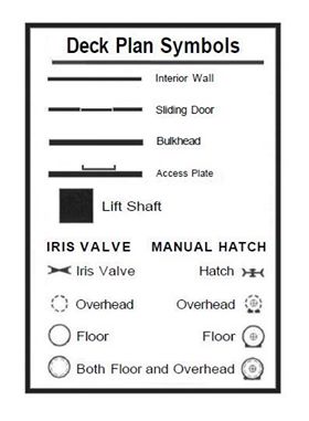
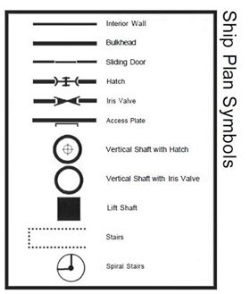
| Deck Plan Symbols | |
|---|---|
| Late Key Diagram | Early Key Diagram |

|

|
Interior Details
Interior Details: The specific interior fittings for ships are fairly standardized, and are shown on the deck plan symbols chart and on many of the individual ship plans as well:[5]
- Airlock
- Bulkhead Wall AKA Bulkhead
- Cargo Hold
- Fuel Scoop
- Hardpoint AKA Ship's Hardpoint
- Hatchway
- Hull
- Interior Wall
- Iris Valve
- Landing Gear
- Lift Shaft
- Maintenance Hatch
- Manual Hatch
- Refrigerated Hold
- Secret Cargo Hold
- Ship Environmental Control
- Ship Life Support
- Sliding Door
- Standard Door
- Viewport
Interior Fittings
The plans show various furnishings and fittings which appear within the ship:[6]
- Common Room
- Emergency Locker
- Fresher
- Galley
- Grav Plate
- Head
- Hydroponics
- Inertial Compensator
- Lab Space
- Life Support
- Low Berth AKA Cryo Capsule (Cold Sleep)
- Mail Vault
- Mess
- Ordinance Locker
- Secure Locker
- Ship Furnishing
- Ship's Locker
- Ship's Magazine
- Ship Module
- Sick Bay
- Spin Habitat
- Stateroom
History & Background (Dossier)
Deck plans, blueprints, engineering schematics... they are all part of successful engineering design and documentation practices. Every successful and technically competent sophont society uses them. And naval architects use them extensively. The Travellers' Naval Architecture Society mandates the use of deck plans throughout Charted Space and is the dominant regulatory body for space and starship architecture across polities, sophont species, and the greater, shared interstellar civilization. [7]
Horizontal vs. Vertical Deck Plans
In space, the only "up" is towards the direction of travel while the "up" in a gravity well is to center mass. This has long been a consideration within schools of naval architecture. Ships dedicated to space travel tend to orient towards the direction of travel until the development of the grav plate. Aircraft, Interface Craft or Spaceplanes, and those spacecraft needing to make planetary landings tend to orient horizontally. Its cheaper to orient vertically towards the direction of travel, even with grav plate technology... The culture of Charted Space tends to build craft with horizontally oriented designs, but does it have to be that way? [8]
References & Contributors (Sources)
- Jordan Weisman. "Book 2." Adventure Class Ships Volume 1 (1982): 3-6.
- Marc Miller. T5 Core Rules (Far Future Enterprises, 2013), TBD.
- Traveller Wiki Editorial Team
- Author & Contributor: Lord (Marquis) and Master of Sophontology Maksim-Smelchak of the Ministry of Science
- ↑ Jordan Weisman. "Book 2." Adventure Class Ships Volume 1 (1982): 3.
- ↑ Jordan Weisman. "Book 2." Adventure Class Ships Volume 1 (1982): 3.
- ↑ Jordan Weisman. "Book 2." Adventure Class Ships Volume 1 (1982): 3.
- ↑ Jordan Weisman. "Book 2." Adventure Class Ships Volume 1 (1982): 4.
- ↑ Jordan Weisman. "Book 2." Adventure Class Ships Volume 1 (1982): 4.
- ↑ Jordan Weisman. "Book 2." Adventure Class Ships Volume 1 (1982): 5.
- ↑ Information provided to the library by Maksim-Smelchak
- ↑ Information provided to the library by Maksim-Smelchak
